
电子电路模电数电计算器
Single-layer coil inductance calculator
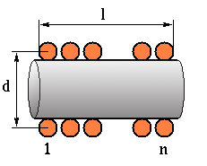
Most of the formulas for the inductance of a coil are valid for the current sheet approximation, where the current flows in an indefinitely thin surface around the coil diameter. This is the same as assuming the coil wound with an indefinitely thin tape with negligible separation between turns. If the separation between turns is not small, a correction factor should be applied. Moreover, at high frequencies the current crowds towards the inside of the coil so the effective radius where the current flows become smaller. Sometimes it is suggested to use the internal radius of the coil instead of the wire mean radius in the calculations, in order to compensate for this effect. However the difference between the low- and high-frequency inductances is usually not large [1]. To compute accurately the inductance of any kind of coil (or also of more complicated conductiong structures) one can use an electromagnetic simulator, as explained here. Regarding current sheet inductance formulas for single-layer coils, one of the most widely known is the one by Wheeler [2], which states (after converting to metric units):
where d is the coil diameter in meters, n the number of turns and l the coil length in meters. The above formula is accurate within 1 % for l>0.4d ; for shorter coils one can use the well-known Nagaoka formula [3] (which has the inconvenience of requiring a list of tabulated values for different diameter/length ratios) or other asymptotic approximations [4]. Some useful formulas, applicable for any diameter to length ratio, are presented in [4] and [5]; the following form implements the latter, for which the maximum relative error is stated to be less than 3 ppm. The Q value is computed here using the formula of [6]; take the resulting value with care, since the limits of validity are not clear to me.
单层线圈匝数与电感计算器
这是最常用的绕线圈场景:手上有一根固定直径的骨架,想知道绕多少圈能得到目标电感。工具以匝数为主输入,给出电感与线长,也可以反过来由电感求匝数,适合 LC 滤波器、天线加感和谐振回路的手工制作。
使用方法
- 填入骨架直径、期望的绕线长度
- 输入匝数得电感,或输入目标电感得匝数
- 读取漆包线用量与直流电阻估算
计算公式
| 电感 | L(µH) = (a² · N²) / (9a + 10b) a、b 单位 cm |
|---|---|
| 匝数 | N = √(L · (9a + 10b)) / a 反解目标电感 |
| 直流电阻 | Rdc = ρ · ℓ / S ρ 铜约 0.0175 Ω·mm²/m,S 为导线截面 |
计算示例
- 9a + 10b = 4.5 + 15 = 19.5
- N = √(1 × 19.5) / 0.5 ≈ 8.8,取 9 匝
- 线长 ≈ 9 × 2π × 0.5 ≈ 28 cm
要点与常见误区
- 实测电感常比计算值高 5%~10%,留出可拆匝的余量更方便调试。
- 骨架直径测量要含漆膜厚度,细线时这几丝的差异会影响结果。
- 绕好后把线头焊住再测,松散线圈的电感会随形状变化漂移。
常见问题
- 匝数算出来是小数怎么办?
- 四舍五入取整,再回代公式确认电感偏差;若偏差超过 10%,可微调绕线长度。
- 空心线圈能做多大电感?
- 受体积限制,空心单层一般做到几十 µH,再大需要多层或加磁芯。
- 为什么测出来比算的小?
- 常见原因是匝间有间隙导致实际绕线长度大于设计值,或者线径细、测量夹具有附加电感。